Calibration
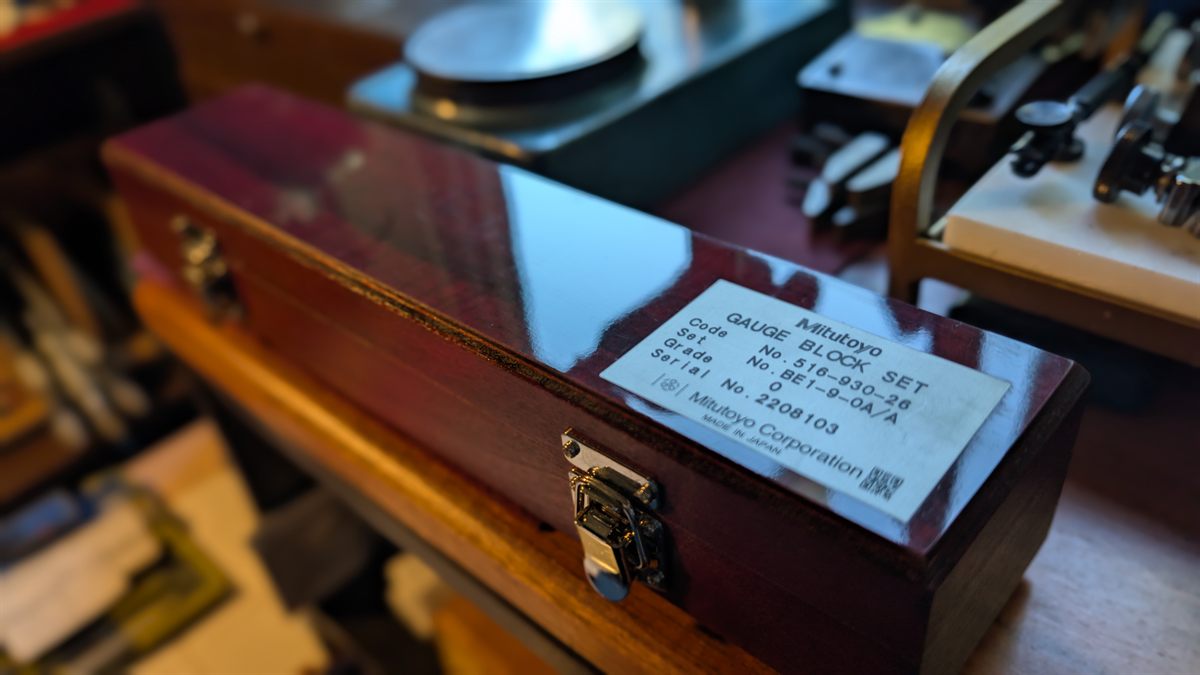
Indicator service — Accuracy verified at multiple positions throughout the full travel range of the device. Every indicator is read on the bench's calibration rig, and the rig is checked against a grade 0 gage block set calibrated by an accredited laboratory — standards traceable to NIST.
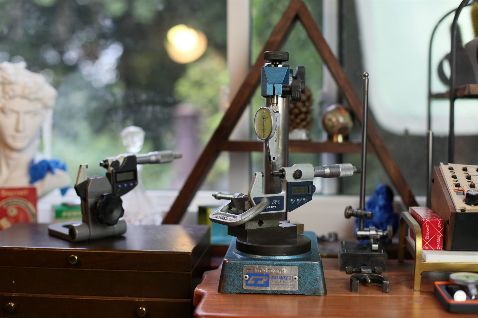
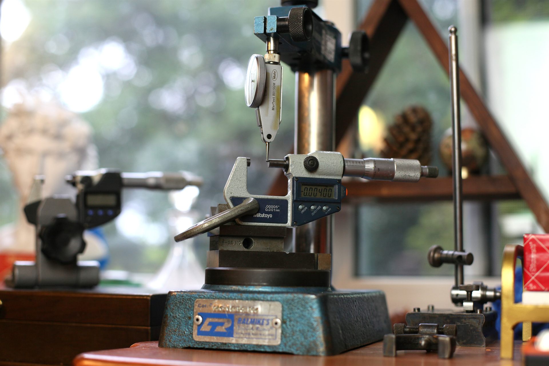
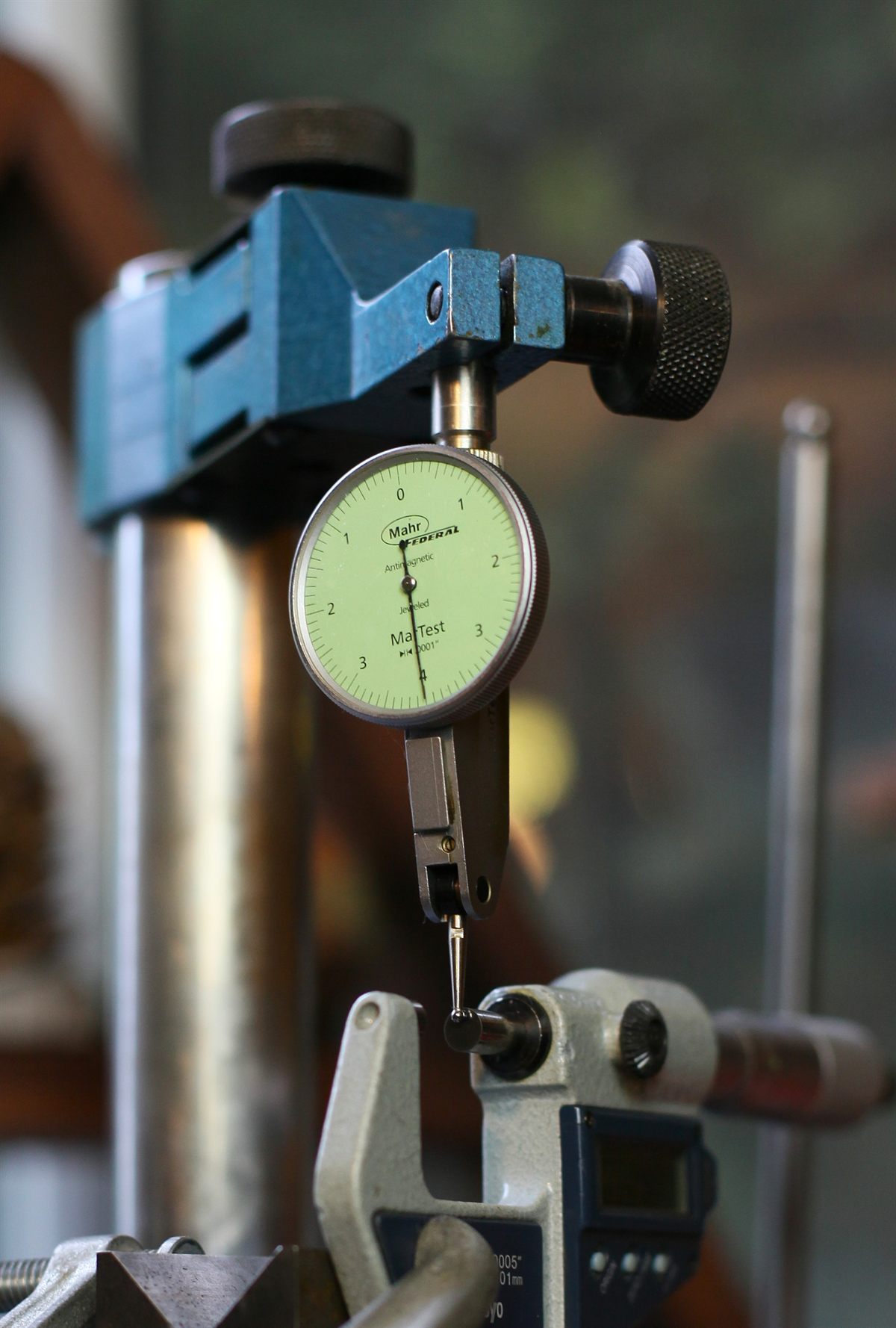
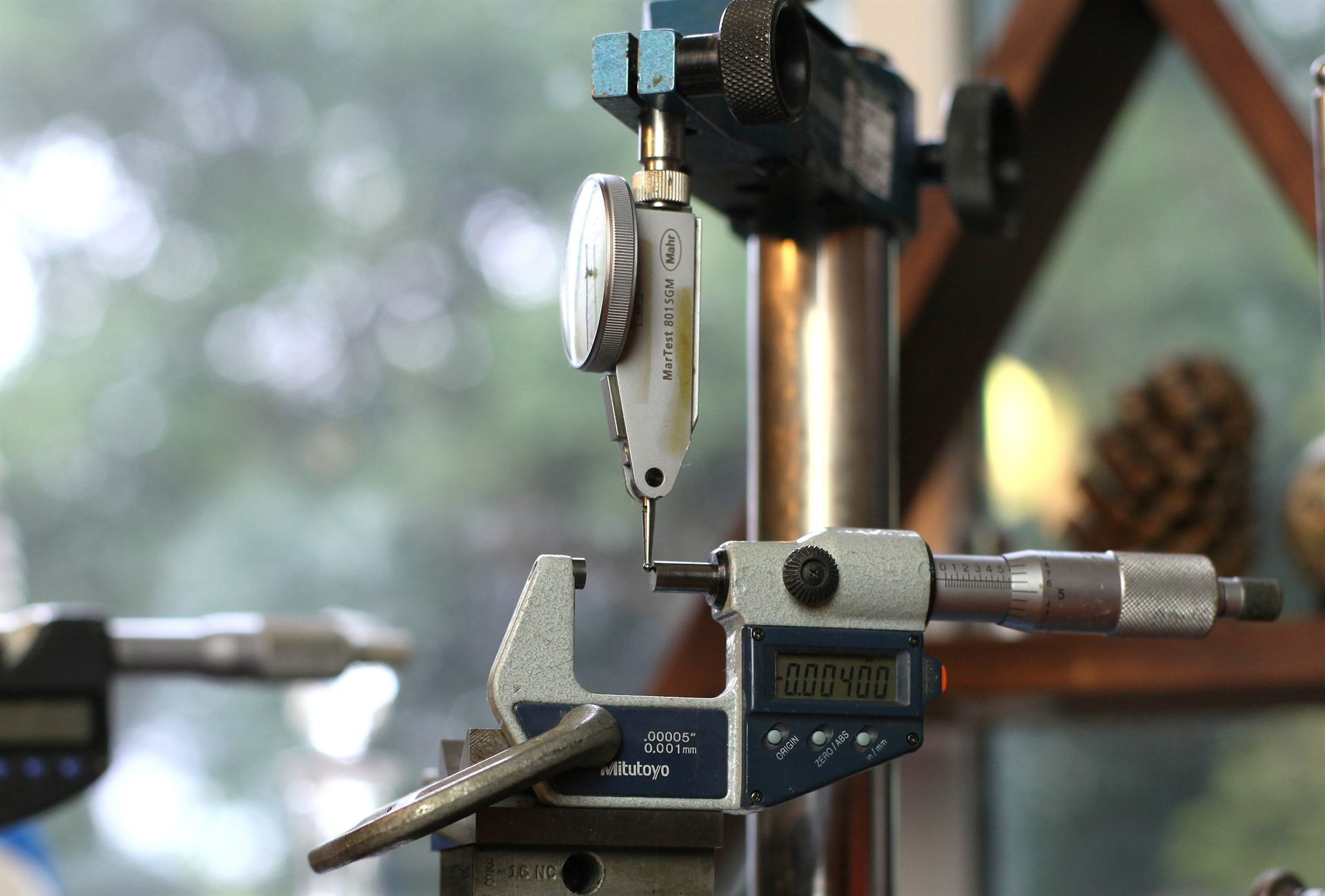
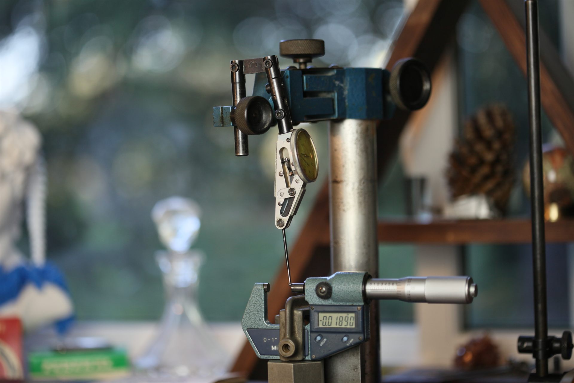
Verification rig
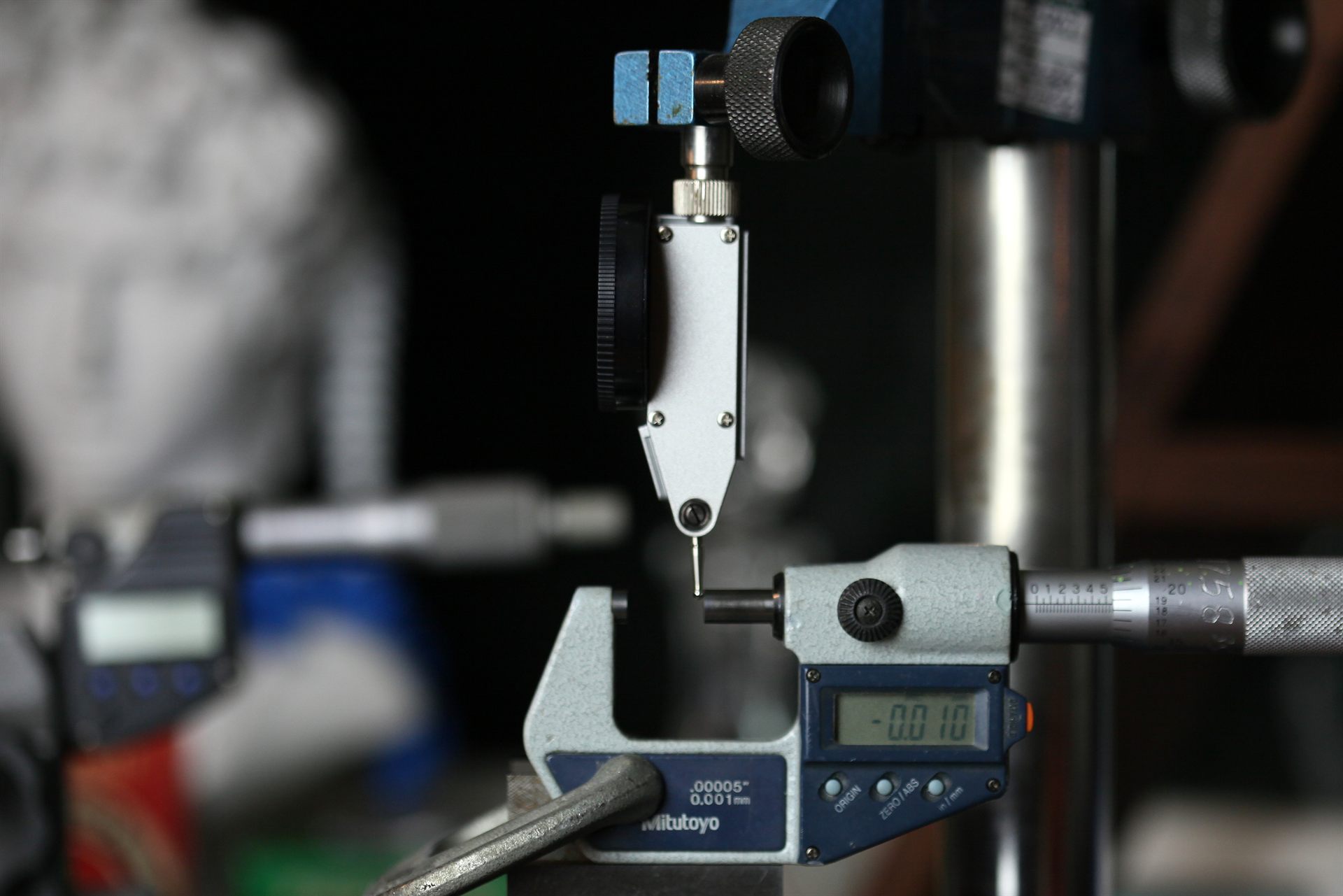
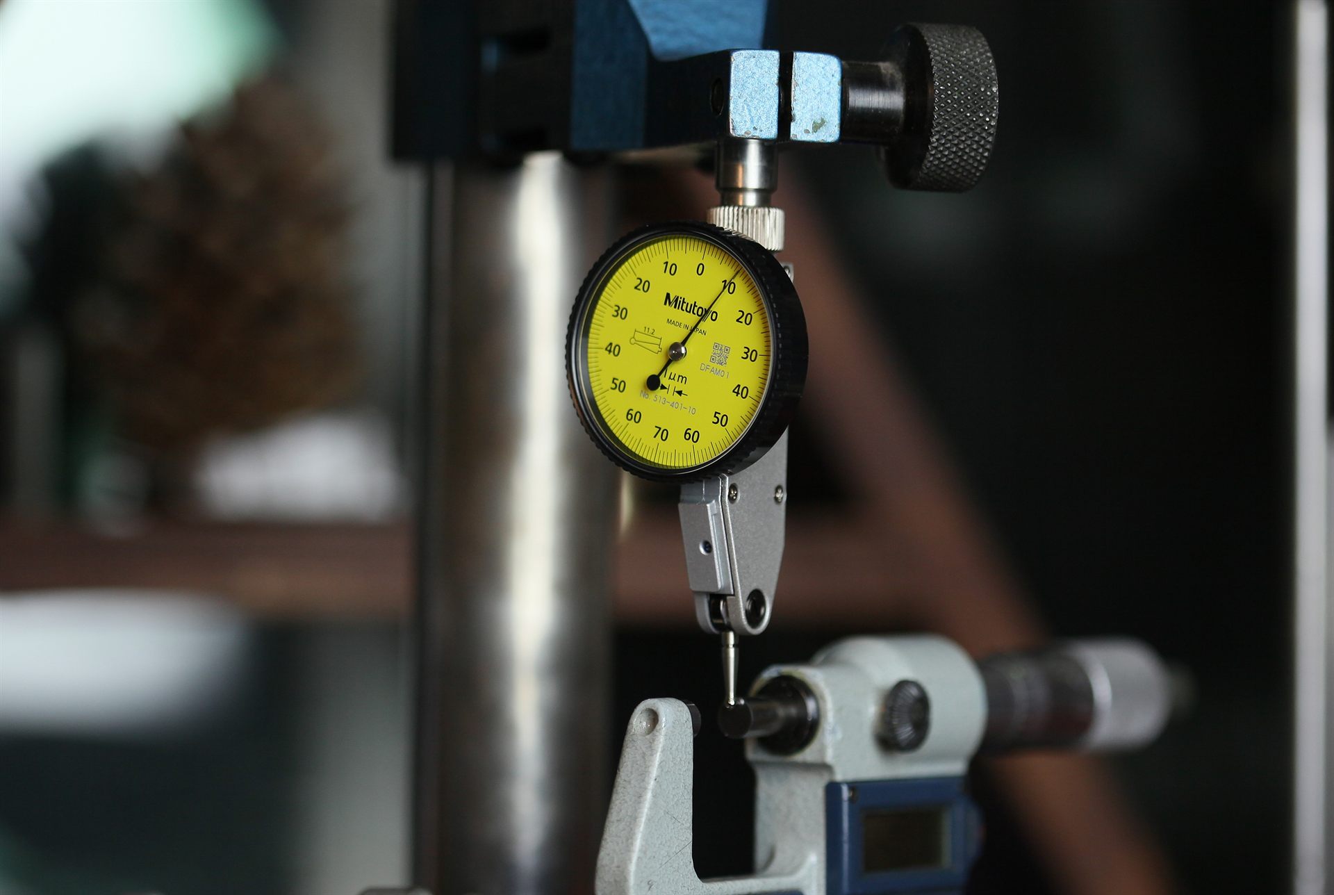
A rebuilt indicator is only as good as the proof that it's accurate. That proof rests on the same process I use to verify a micrometer to be accurate: the spindle displaces the indicator's contact point in known increments, and the two readings are compared.
Intentionally simple in design to reduce variables to the minimum. A reference you don't control is another dependency — a dependency which is mitigated by the simplicity of this design.
Everything the rig says about an indicator rests on the micrometer being verified and calibrated, and so that is the main process my calibration routine focuses on and maintains complete self-reliance in — no part other than the standards themselves has to be sent out to be recertified/calibrated.
2 Processes- 1 CALIBRATION ROUTINE
The indicator calibration Rig is a micrometer and verifying it is the same as verifying a micrometer and indicating it square.
A nine-block micrometer inspection set is used. The round values — .100 through 2 inch — starting from 0, check the micrometer across its range.
An optical flat and parallel ride with the set and check that the measuring faces are flat and parallel to each other. Optical flat only comes out if the anvil faces fail the ball test, where a series of measurements are taken with a small ball gage in different positions on the faces. Variance in measurement = variance in faces being flat or parallel.
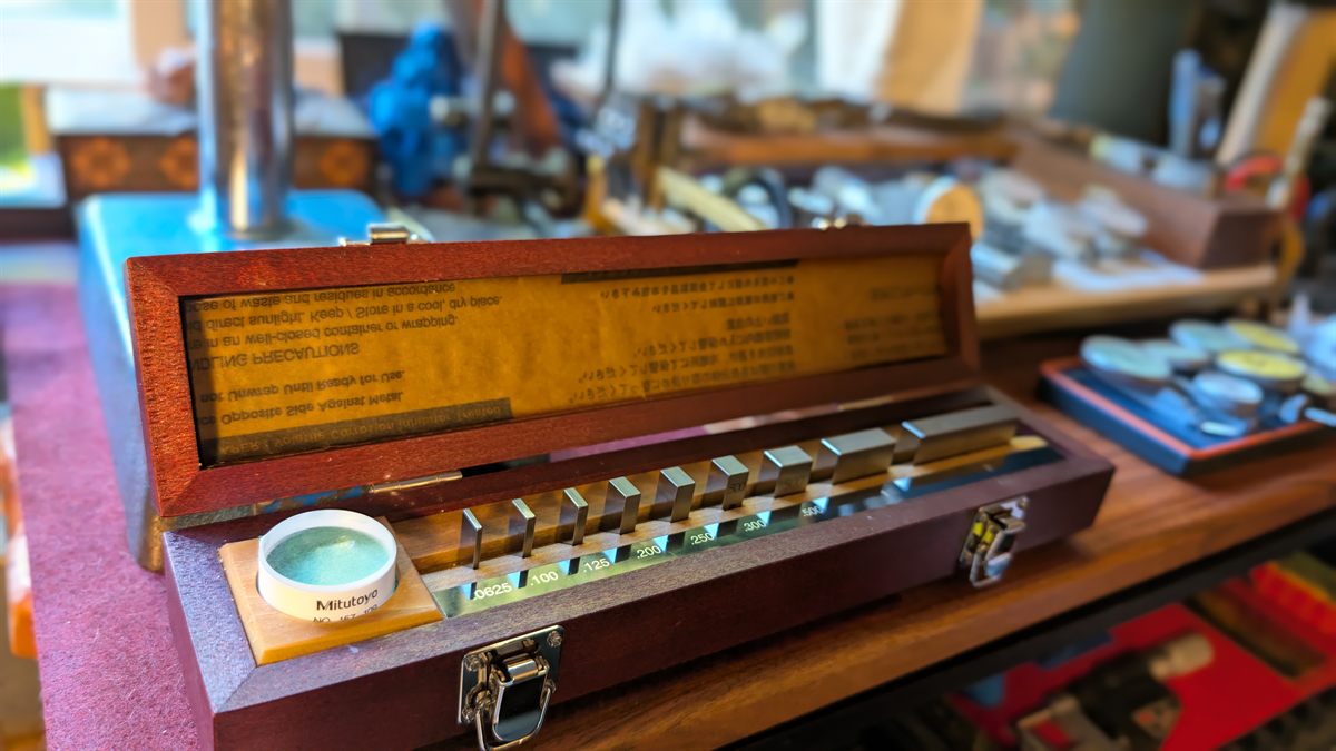
Master reference- Joe blocks
Grade 0 under ISO 3650 and ASME B89.1.9: each block within 0.14 micrometre of its marked length up to 25 mm, 0.20 at the inch and 0.25 at two inches — five to ten millionths — and no more than 0.10 micrometre of variation across its face.
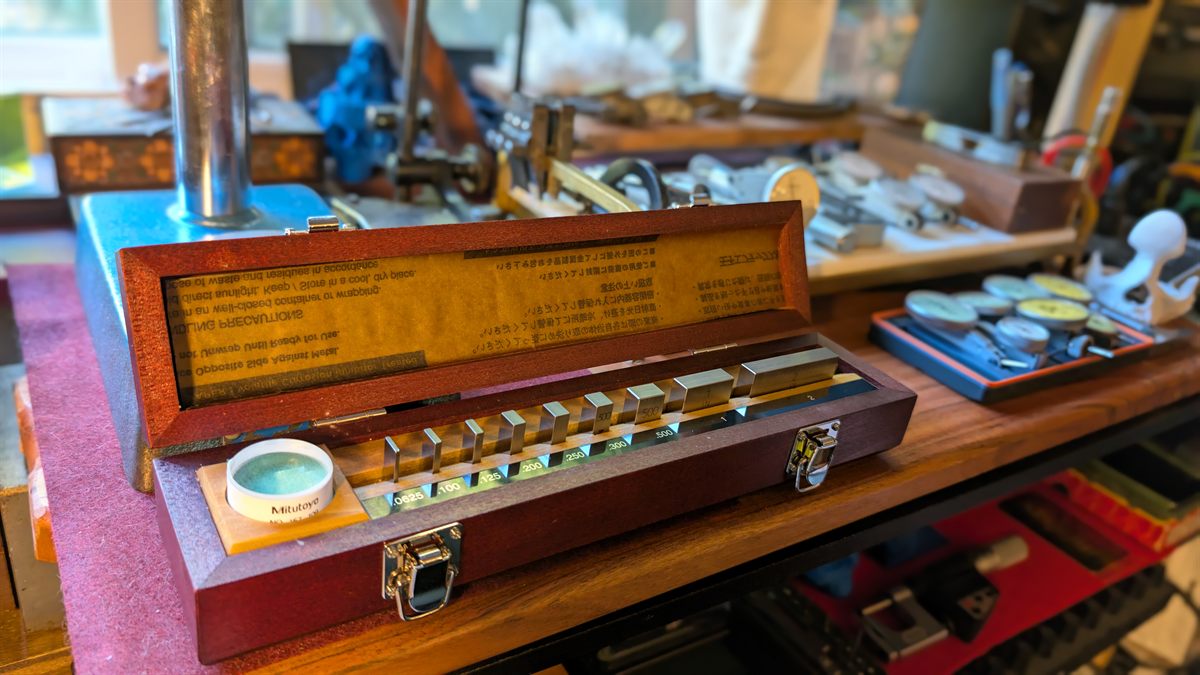
When a check needs to go further
Two angles miss an error that peaks a quarter turn away. When a check turns up something inconsistent, or a figure is going on a certificate, the micrometer goes to a ten-block staggered set — .105, .210, .315 and so on to the inch. Each block lands the thimble a fifth of a turn round from the one before, so five blocks carry the spindle through a full revolution. A micrometer whose error grows along its travel and a micrometer that reads true at some angles and not others are different faults; only a sequence that moves around the rotation tells them apart.
The budget
| Contributor | Limit | Distribution | u (µm) |
|---|---|---|---|
| Block length, grade 0 at 1 in | ±0.20 | rectangular | 0.115 |
| Block face variation | ±0.10 | rectangular | 0.058 |
| Micrometer residual after block check | ±0.60 | rectangular | 0.346 |
| Thermal, block vs micrometer at 1 K | ±0.29 | rectangular | 0.169 |
| Comparison repeatability | — | type A, from data | 0.200 |
Combined 0.45 µm; expanded (k = 2) 0.9 µm. Against an indicator specified at ±.0002 inch that is over five to one, past the four-to-one convention. Every term here can be re-taken on demand.
What the numbers mean
Half a micron sounds like precision for its own sake until it's set against the thing being checked. A .0005 inch indicator is fourteen times coarser than this rig's uncertainty; the rig is not its limit.
A 1 µm indicator is where the number earns its place. It leaves this bench checked against a micrometer whose error is known to a fraction of a graduation, with the uncertainty stated, and every term of it re-takeable here. That is what the budget is for, and what irreducible means here.
Hysteresis in lever-type test indicators
Accuracy across the range is one axis; a lever indicator can also read differently on the way out and on the way back. The library holds an interactive module on where that error comes from and how it is measured.